|
3D Graphics on Mobile Devices - Part 4: Polygon Rasterization by (03 September 2003) |
Return to The Archives |
Introduction
 |
| This is the last part of the series of articles on 3D graphics for mobile devices. In the previous article I described the racing game we developed at Overloaded. There's one piece that is still missing: Polygon rasterization. This final article will describe the rasterizer I implemented for Fantom Overdrive. |
|
Polygon Rasterization
|
|
In this age of hardware accelerated polygon rasterization nobody cares about exactly how a single polygon is drawn on the screen. Instead the interesting stuff is done by a GPU and all the programmer has left to do is boring stuff. Not on mobile devices though. Let’s brush up on classic software polygon rasterization a little: A polygon is a mathematical shape, a 2D area bound by a set of line segments. On screen however, it’s an approximation; the edges start looking like stairs and the interior is filled with small rectangles with varying colors. The screen is a raster, and thus polygon rendering is called ‘rasterization’. The polygon is reduced to a set of horizontal lines (or vertical, of course). When the resolution of the raster is high enough, our eyes believe that we actually see the original mathematical shape. The whole rendering process is of course one big fake show: Besides the polygons that consist of rectangles you are watching a 20 frames per second slideshow. In the end all that matters is wether or not your eyes believe what they see, so it’s important to focus on ‘perceived quality’. I encountered a good example of this a couple of years ago. I had a spinning meteor, shaded with gouraud shading, running at 30fps. Then I added ‘fake phong shading’. The frame rate dropped to 20fps, but with much higher image quality, it looked smoother. The perceived quality increased. Another example of ‘belief’: I once implemented reflective surfaces in a software renderer. I took a very simple approach: The object simply was textured with the previous frame. Despite the fact that the object appears to reflect itself, the eye has no problem at all with believing that the object is really reflective. Apparently, eyes don't do many calculations on reflections to verify that they are real. I found that eyes are not too picky about shadows either. So let's have a look at basic polygon rasterization. I decided to use ‘n-gons’, not just triangles (see previous article). N-gons are best rendered by tracing the edges, storing them in outline tables (wich contain two x-coordinates per scanline) and finally drawing horizontal lines of pixels between these two x-coordinates for each scanline. Here’s some code:
where y1 is the scanline where the edge starts, y2 is the last scanline, cx is the start x position of the edge, dx is the slope of the edge and m_Left / m_Right is the outline table. The ‘cx’ is an interesting variable. I just said it is the start x position of the edge, but that is not accurate. Check out this line rasterization: 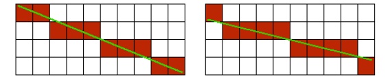 Note that both lines start in the top-left pixel and end at the bottom-right pixel. So when we are working with just integer coordinates, both lines should be equal. But when we take the sub-pixel position of the line coordinates into consideration, the two lines are no longer equal. Now check the code snippet again. The scanline indices y1 and y2 are integer, since we want a pair of x-coordinates per scanline. The ‘cx’ variable however is fixed point. So when a line starts at x = 10, y = 1.5, we still start rasterizing at y = 1. Now suppose the slope is 2, and x = 10 when y = 1.5. Then x should have been 9 at y = 1.0. If you think this is not a big deal, you're wrong. Working with integer coordinates or omitting sub-pixel correction results in polygons that shake noticeable. With perfect sub-pixel correction, a very cool effect occurs: Your raster display starts to look like a set of small lenses through which you view a world that is perfectly accurate. This effect is so strong that you can get away with a lower resolution with sub-pixel correction. For a very cool demonstration of sub-pixel accuracy, fire up a copy of Quake 1 and complete a level. The level statistics screen has a camera view that moves very slightly. You see the ‘pixel stairs’ gently moving across the polygon edges, and you get the impression that you’re looking at a world that is much more detailed than what the raster is able to display. Here is a code snippet for the sub-pixel correction I just described:
(where sy1 is the fixed point (16:16) screen coordinate of the first vertex of the edge). ‘Fix’ is the one minus fractional part of the fixed point coordinate. This value is multiplied by the slope of the edge and added to the x-coordinate of the first vertex of the edge. |
|
Texturing
|
Check out the following image: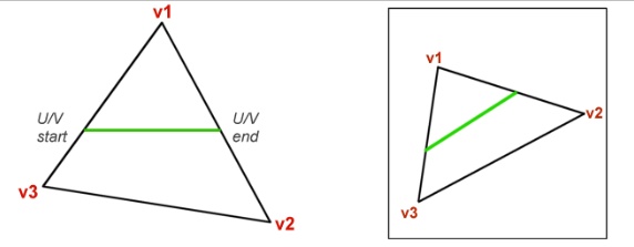 Here we have an n-gon consisting of three vertices (v1, v2 and v3). The horizontal green line on the triangle is a scanline that we wish to draw. The triangle is textured. To get the u and v coordinates for the green line, we interpolate u and v over the edges. To get u and v for each pixel on the green line, we interpolate u and v in texture space (right image). The u and v coordinates need to be corrected just like the x-coordinate to compensate for the integer y coordinates of the scanlines. So, we expand the snippet that fills the outline tables to interpolate u and v as well:
Most of this code should be self-explanatory, except for the odd line that keeps track of the maximum width of the polygon. There is a very good reason for keeping track of the widest span: It is used to calculate the slope of the spans in texture space only once for triangles. If you go back to the above image, and try to add some extra lines, you’ll notice that the lines in texture space are all parallel. Since calculating the slope of this line requires a division (and divisions are expensive), it’s worthwhile to exploit this. The slope can be calculated best with the widest span, since this gives the best accuracy. Here’s a snippet for the slope calculation:
If the polygon has three vertices and the widest span is more than zero pixels wide, then du and dv are precalculated for the entire polygon. |
|
Perspective Correction
|
All 3D accelerators are capable of perspective correct texture mapping. To see why this is needed, have a look at the following image: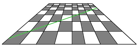 Suppose we are tracing the green line in screen space and texture space, like we did earlier for the triangle. If you start on the left side, you’ll notice that a couple of screen pixels represent a far smaller length in texture space then the pixels at the end of the line. We can no longer interpolate linearly in texture space. We could simply ignore this, and in fact lots of older games do this. The PS1 doesn’t have hardware with perspective correction either by the way. For the racing game, I found this unacceptable, especially for the road polygons. You’re watching the road closely the entire race, so it needs to look good. Perspective texture mapping is implemented by interpolating u/z and v/z instead of u and v. U/z and v/z can be interpolated linearly, but you must retrieve u and v for each pixel in order to be able to fetch a pixel. This can be done by dividing these figures by z again. So we interpolate u/z, v/z and z and perform two divisions per pixel… Yeah right. There are tricks to get this faster, but let’s ignore that for the moment. There’s something funny about the road: It’s always horizontal. If you look at the chess board again, you’ll notice that while the green line can’t be interpolated linearly in texture space, any random horizontal span of the chess board can be interpolated linearly. On a horizontal line, each square has the same size, although it differs for each scanline. This is called ‘constant z-slope’. For each pixel on the horizontal line, the depth is the same. This means we still need to interpolate u/z and v/z over the polygon outlines, but when drawing the spans, we can simply interpolate u and v again. With the improved edge tracing, the road polygons now look rock solid. |
|
Performance
|
|
I already mentioned several ways to cut down on the number of divisions needed for rasterization. There’s one more cool technique: Winged edges. This is a simple technique that links polygons that share the same edge. By storing the results of certain expensive calculations in the edge object the results can be re-used when the edge is needed again. The winged edge struct looks like this:
The winged edge structure for a mesh is calculated by finding shared edges; for each edge of each polygon you search through all other edges of all other polygons to see if there’s a match. If so, a pointer to the neighbouring polygon is stored in the object. A gentlemen from Autodesk once mailed me with a better way to calculate the winged edge structure: After loading a 3D mesh, you probably already have a list of coordinates for the vertices. For each coordinate, make a list of vertices that use the coordinate. Now the number of polygons that need to be checked is much smaller. Note that for a perfect winged edge structure you need a very clean and closed mesh. No gaps, never three polygons on one edge. |
|
Last Words
|
|
That’s about it. I hope you enjoyed reading the articles. If you have questions left, don’t hesitate to drop me an e-mail at jacco.bikker@overloaded.com. Greets Jacco Bikker, a.k.a. “The Phantom” |
|
Article Series:
|