Light Mapping - Theory and Implementation
by (21 July 2003)


Return to The Archives
Introduction


Ever since the days of Quake, developers have extensively used light mapping as the closest they can get to realistic lighting. (Nowadays true real-time Per-Pixel-Lighting is slowly replacing light maps).

In this article I am covering a simple but quick light mapper that we developed in 2001 for use in our internal projects at Dhruva Interactive. The method is not as precise as radiosity based techniques, but nevertheless produces results that are effective and usable.

This article will be useful for people who haven�t got light maps into their engine / level yet, and are looking for relative resources.


Overview


This document explains / demonstrates the process of creating light maps for use in games or any graphics application.

Objectives

The goal of this document is to explain the process of creating light maps. It describes how light map lumels are calculated and how the final pixel color is determined.

However, this document does not cover any of the latest �per-pixel� techniques that are possible with the new generation graphics chipsets.

Assumptions

It is assumed that the reader has in depth knowledge of 3D game programming and the essentials of 3D graphics, especially lighting, materials, 3D geometry, polygons, plane, textures, texture co-ordinates, etc.

Also, this document explains only the process of light map evaluation or generation � it does not explain how light map texture co-ordinates are calculated. If you do not have light map texture co-ordinates in your mesh yet, then, I�ve got a simple method to test the light map generation.

Click here to read more on this.

If you are really eager to know the results of a light map based lighting technique before you get on with this article, then click here to go to the demo section, where you can download an interactive demo.


Lighting Basics


You've seen games which look pretty close to real life ambience (I mean, only look wise). The reason for that, is the use of lights. If the game was not "lit", then, it would look less than ordinary. It is the lighting, which makes the player, look at the game again and again. 
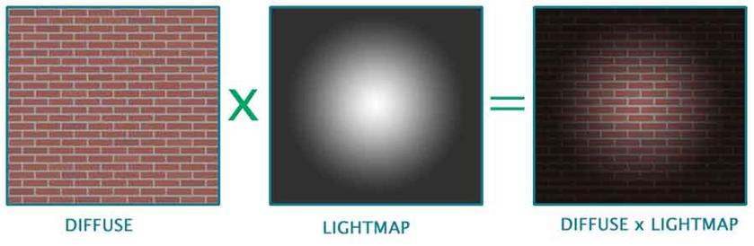
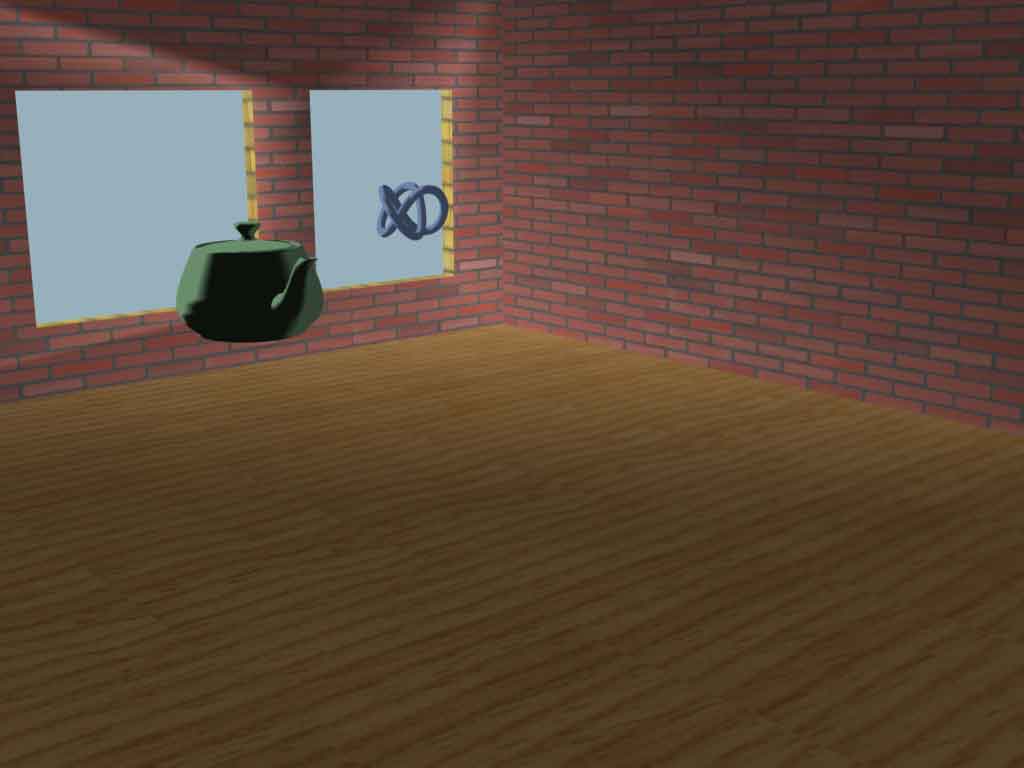
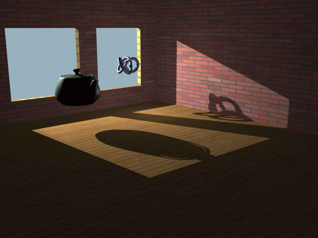
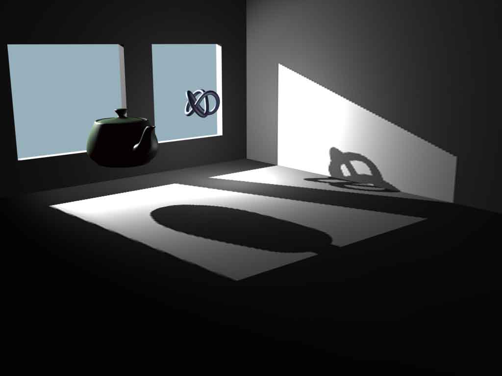
Take a look at what difference, lighting makes:


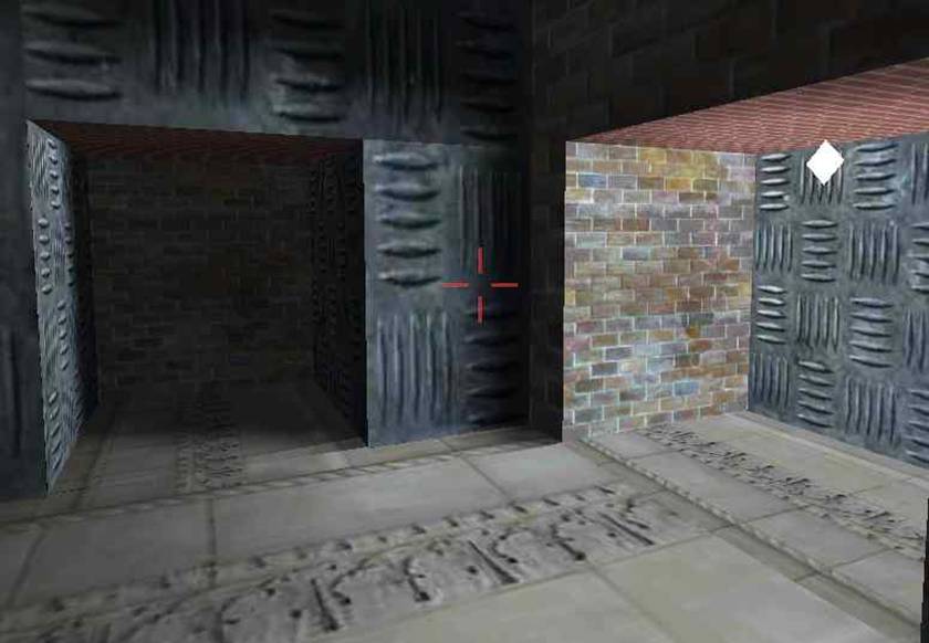
World with light-map lighting. The white rhombus type object (on the right hand side) represents a point light source.


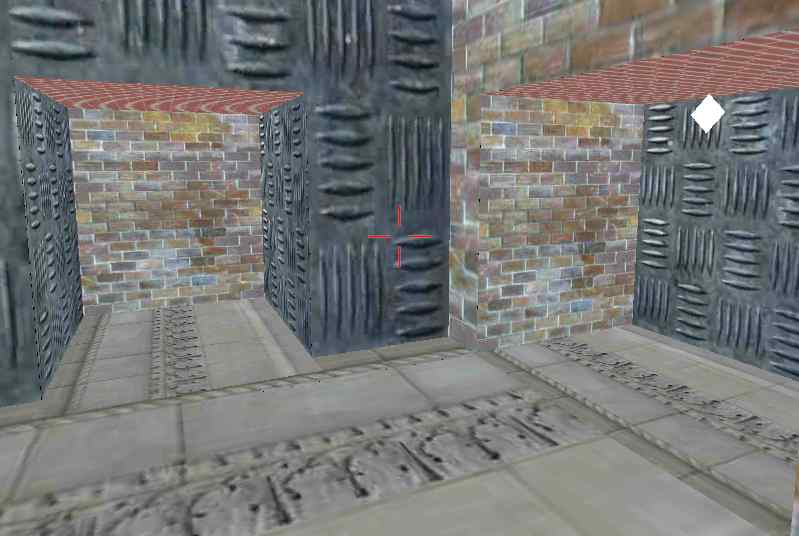
World without any lighting.


The results are impressive, aren't they?

Now that you�ve seen the results, let�s take a look at the different types lighting in practice (as far as the "static world" is concerned).

1. Vertex lighting:
  • For every vertex, a color value is calculated, based on how lights affect it.
  • The color values will be interpolated across the triangle.
  • Triangles / polygons cannot be very large, other wise which visual glitches will be seen.
  • Polygons have to be tessellated to a decent level for the output to be good.
  • If vertex count goes up, then, calculations also take longer � since it is per vertex based.
  • Does not incur a load on texture memory (as required for light maps).
  • All the calculations are done in real time � hence real-time lighting is very much possible.
  • Shadow(s) are not correct.
  • Can achieve amazing lighting effects.
  • 2. Per-pixel lighting (Real time):

    This document does not cover the per-pixel lighting methods that are in practice today, i.e., the effects that are achievable on current generation of graphics cards, like NVIDIA GEForce 3/4, ATI Radeon 8500/9700 and later.
  • For every pixel that is going to be drawn, calculate the color value based on how lights affect it.
  • Does incur a huge load on the engine.
  • It is not practical for a real-time game to use it.
  • Accurate shadows are possible (another overhead with collision detection is a certain possibility).
  • Can achieve the most realistic lighting possible � but is too slow to use in real time games.
  • 3. Per-pixel lighting (light map):
  • Realistic lighting can be achieved.
  • Dynamic lighting needs a lot more work.
  • Can combine with vertex lighting to achieve real-time dynamic lighting.
  • Every single bit of expensive lighting calculation is done during pre-process time.
  • Hence, no overhead during runtime.
  • At run-time, all calculations (color arithmetic) are done by hardware. Hence it is very fast.
  • Visual quality of the lighting is directly dependant on the size of the light map texture(s).
  • The closest we can get to per-pixel lighting, with such less overhead.
  • For every triangle, a diffuse texture map is applied first and then, a light map is usually modulated (multiplied) with it.


  • Per-pixel Lighting Using Lightmaps


    We will be discussing light-map based lighting in the remainder of the document. A light-map is nothing but another texture map. The only difference between a light map and a diffuse map is that, a diffuse map holds plain color values, whereas, a light map holds color values as a result of light(s) affecting the polygons on which this light map was applied. Everything else is the same.
  • Light maps textures are mapped to a triangle/polygon using a unique set of texture co-ordinates known as light map texture co-ordinates.
  • Resource for light map is loaded the same way as the diffuse textures.
  • Each pixel in a diffuse map texture is usually referred to as �texel�, whereas each pixel in a light map texture is referred to as �lumel�. We all want to use fancy words � don�t we???
  • Before delving into the process of light map calculation, lets take a look at how a 2D texture is mapped on to a 3D triangle.


    On the left hand side of the above diagram, is a 2D texture (as you would see in any of the image editing tools) of (N x N) dimension. The normalized dimension is also shown.

    On the right hand side is a 3D polygon, as you would see in the game, except that the background is missing. The texture co-ordinates are mentioned for each vertex. As you can see, the texture is mapped to the polygon with a mapping ratio of 1:1. i.e. the whole texture is mapped to the polygon at a ratio of 1:1.

    Now consider the diagram below. The diagram shows a polygon being mapped or pasted on a 2D texture. This polygon however uses only a part of the texture. So, the mapping ratio is not 1:1. We can observe that the polygon covers a only a part of the area of the complete texture. i.e. this polygon has some pixels from the texture map belonging to it. Hence, more the pixels that this polygon has, the more nicer that this polygon will look. (This is in 3D viewing, considering the camera is neither very close to the polygon nor far from the polygon. We shall ignore MIPMAPS for this discussion).


    Let�s look at the above diagram closely taking light maps into account. A diffuse map, may or may not be shared by polygons. i.e. a pixel from a diffuse map can be belong to "n" number of polygons. But, for a light map, a pixel belongs to one and only one polygon.

    Each pixel in the light map has a corresponding position in the world, with respect to the polygon that it belongs to. You have to understand this concept very well. Since every vertex of a triangle has a position in the world, every light map pixel that this triangle will hold will have a position in the world � which will vary uniformly across the length of each edge.

    Also, there is a concept of pixel center. Whenever we refer to a pixel, it means the pixel center. A pixel is not a point, but it is a box. Please refer to the diagram below.


    Based on the above criteria, whenever we want a UV co-ordinate for any pixel, it is calculated this way:

    
    x = (w+0.5) / Width
    y = (h+0.5) / Height


    In the above equations,
    w and h = offsets for the current pixel that we are calculating UV co-ordinates for.
    Width = width of the light map texture.
    Height = height of the light map texture.

    This is what is mentioned in the diagram below.


    Now, I�m trying illustrate what I have said above, in the form of a diagram. First, take a look at the diagram:


    In the above figure, I am hypothetically describing the relationship between the triangle and the (light map) pixels.

    In the above figure,
  • the triangle is defined by the 3 thick black edges / lines.
  • the three vertices of the triangle are (0,0,0) , (0,100,0) and (100,0,0)
  • Since the Z co-ordinate for all the three vertices is same, we can safely ignore the Z-component for our calculations.
  • Each box inside (and slightly outside) the triangle identify a unique (light map) pixel.
  • Remember that a pixel is a box (has area) and not a point.
  • Green box means, that the pixel is well with in the triangle and that this light map pixel belongs to this triangle.
  • Pink box means that the pixel centers fall outside this triangle and hence these pixels do NOT belong to this triangle.
  • Every pixel that belongs to this triangle has been numbered in certain order.
  • This triangle contains 15 pixels.
  • Our exercise now is to determine the approximate theoretical world position for each pixel just by observing the triangle and the pixels.
  • Remember, what we are doing now is just based on eye measurements. It is in no way accurate.

    This exercise is to just make you understand the relationship between vertex, lightmap texture-cordinates and light map pixels. This exercise should give you an idea of what the "world-position" for a pixel means.

    Look at the bottom most line, there are 5 pixels and the width of the edge is 100 units on X axis.
  • That means 20 units for each pixel.
  • Also, the edge�s position varies only on X axis. So, Y and Z values remain constant.
  • Hence the first pixel would have the X value of 20 (Not accurate by any means).
  • First pixel�s position would be (20.0, 0.0, 0.0)
  • The second would have a position of (40.0, 0.0, 0.0), third would have (60.0, 0.0, 0.0), fourth would have (80.0, 0.0, 0.0) and the fifth would have (100.0, 0.0, 0.0)
  • Similarly, try to arrive at the positions for the other pixels.

    I'm reminding you again that the above results are NOT correct. That exercise was to make you understand what "world-position" for a pixel means.

    Also, from the above diagram, you can decipher that � the more (light map) pixels a triangle has, the lesser will be the world-position shift from pixel to pixel � and hence results in a smoother output. Try to figure out how?

    If you still haven�t understood the concept of pixel center, and world-positions for a pixel, then, please go through this document again from the start. Please do not continue if you are not clear.

    Here�s an image which shows the result of using a light map.


    A Simple Lightmap Based Lighting Technique


    Now let�s get on with the actual process of light mapping. The complete process of calculating light maps is split into three parts. They are:
  • 1. Calculating / retrieving light map texture co-ordinates.
  • 2. Calculating the world position and normal for every pixel in every light map.
  • 3. Calculating the final color for every pixel.


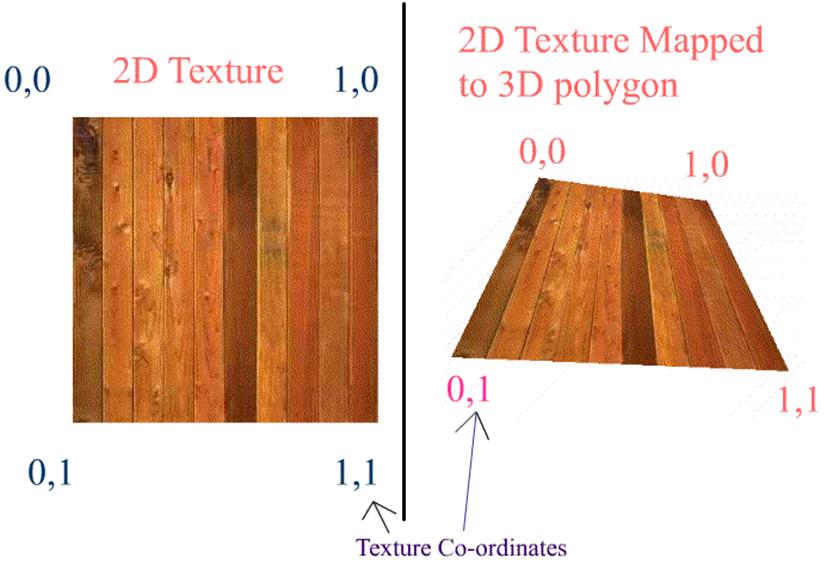
  • a. Calculating / retrieving light map texture co-ordinates:

    This is the very first and basic process. It involves assigning each polygon to a specific area of the light map. This topic in itself is a candidate for a lengthy article. Hence, I'm going to skip this topic and jump to the next one.

    However, if you want links to articles that explain this, then, I've provided some in the links section, at the very end of this article.

    Also, this is one of the most important processes, since it determines the efficiency of using texture space. This can either be done in an automated process or can be done manually in editing tools such as 3DS Max� or Maya�.

    However, if you want a quick way to generate a world to test light maps, then you can do this:
  • Create an empty cube, a pretty large one. (empty, hence collision detection is not required)
  • Assign diffuse and light map texture co-ordinates manually.
  • Even better, you could use one diffuse for all the faces of the cube and use six different lightmaps for each face(polygon) of the cube.
  • This way, you can map the light map to the polygons of the cube with a ratio of 1:1.
  • Create one or two lights at the extreme top ends of the cube.
  • Use this setup to test your light map generation.
  • In the next level, to test shadow generation, you can add a box at the bottom center of the cube, and add collision detection routines.


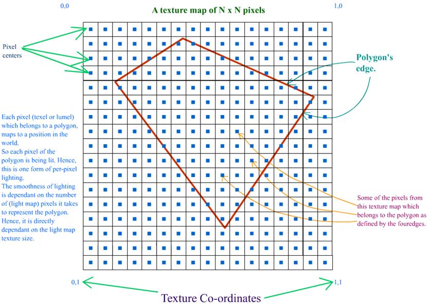
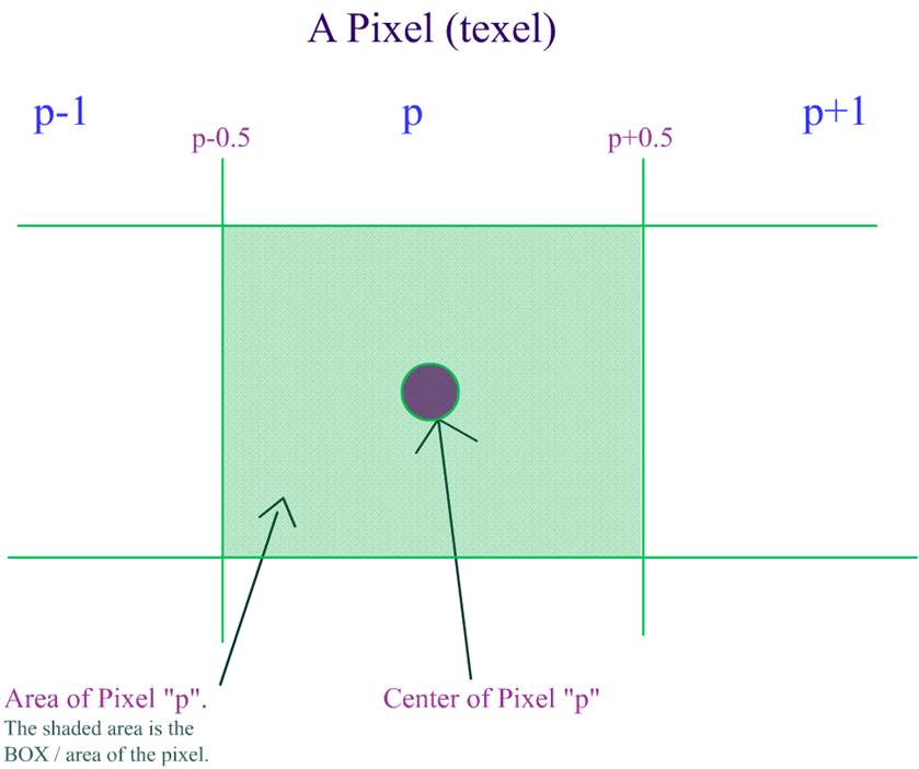
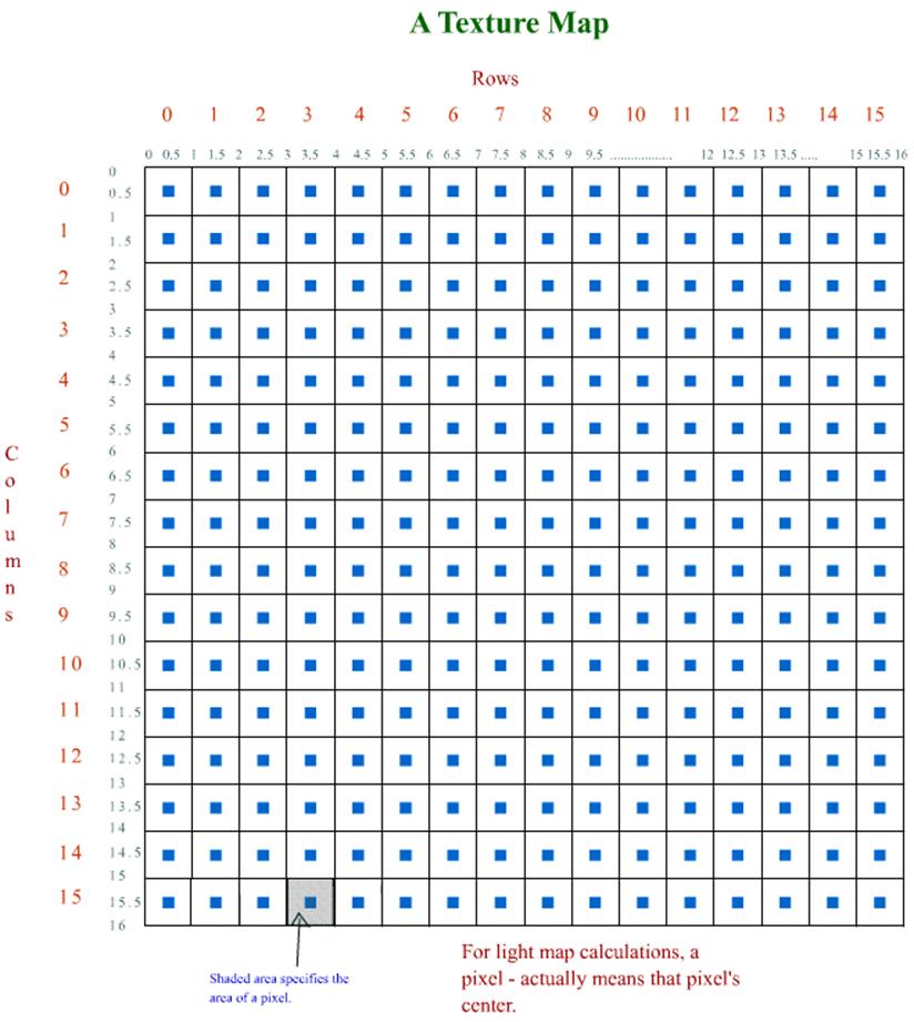
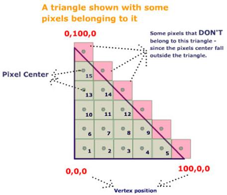
  • b. Calculating the world position and normal for every pixel in every light map:

    This is the pre-processing stage of the light map calculation. As you know, each pixel in the light map will map to a position in the world. This is exactly what we need to calculate. As long as the world geometry and the light map texture sizes doesn�t change, this data is static, i.e. it can be calculated once and reused.

    This is how it is done. Now consider a triangle like this. Why we have only 2D components for vertex position in the below triangle will be explained in later paragraphs.


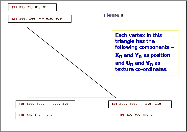
    Let�s see what are all the know factors here:
  • a. We know the end points of the triangle (2D).
  • b. We know the (light map) texture co-ordinates for all the 3 vertices.
  • What do we need to calculate here: Given a texture co-ordinate value (on or within the 2D triangle), retrieve the 2D position on or within the 2D triangle. We have to do it for every pixel of the light map that this polygon owns. (Remember, a pixel from a light map can belong to one and only one triangle / polygon.) Let's see how we can achieve this.

    NOTE: In the following few paragraphs, I�m using certain equations, illustrations and quotes from
    Chris Hecker�s article on Perspective Texture Mapping. Please refer to the above said article for more information.


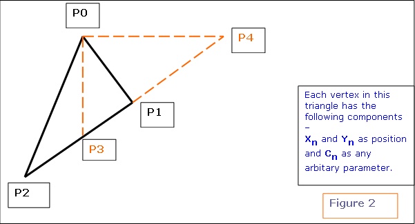
    Consider triangle P0, P1, P2 in the above diagram. Each vertex has a screen space (2D SPACE) associated with it i.e. (X, Y). But in addition, there is an arbitrary parameter, C, which is, color for Gouraud Shading, or 1/Z, u/z or v/z for perspective texture mapping. Hence �C� is any parameter we can linearly interpolate over the surface of the two-dimensional triangle. For the derivation, two points P3 and P4 are constructed as shown in the above diagram.

    Therefore,

    
    x1 - x2      x4 � x2
    --------  =  --------
    y1 � y2     y4 � y2

    and

    c1 � c2 c4 � c2 -------- = -------- y1 � y2 y4 � y2


    We know that y4 = y0 and x3 = x0.

    Click here to see the derivation as to how we arrived at equation 1 and 2 mentioned below. For the triangle, we get the following two equations:


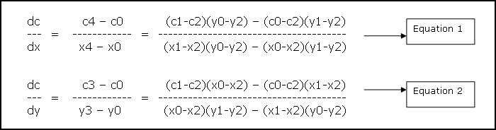
    The above two equations tell how much of variable �C� varies w.r.t X and Y. i.e. given a position (x, y) we can calculate �C� for that position. For our lightmap solution, we need just the opposite. We know the texture co-ordinates (i.e. �C�) and we need to retrieve the position. I will be using the formulas as mentioned below. These are directly inherited from the above two equations. (Please refer to figure 1 for the variable names)

    
    denominator = (v0-v2)(u1-u2) � (v1-v2)(u0-u2)

    dp dx (x1-x2)(v0-v2) � (x0-x2)(v1-v2) --- = --- = -------------------------------------- du du denominator

    dp dx (x1-x2)(u0-u2) � (x0-x2)(u1-u2) --- = --- = -------------------------------------- dv dv -denominator

    dq dy (y1-y2)(v0-v2) � (y0-y2)(v1-v2) --- = --- = -------------------------------------- du du denominator

    dq dy (y1-y2)(u0-u2) � (y0-y2)(u1-u2) --- = --- = -------------------------------------- dv dv -denominator


    Now get uv position relative to the first vertex�s light map texture co-ordinate.

    
    duv.x = uv->x � u0
    duv.y = uv->y � v0


    uv is the pointer to the texture co-ordinate for which the �world-position� has to be computed. U0 and V0 are the light map texture co-ordinates for the first vertex.

    Let pos be the pointer to final position.

    
    Equation 3

    pos->x = (x0) + (dpdu * duv.x) + (dpdv * duv.y) pos->y = (y0) + (dqdu * duv.x) + (dqdv * duv.y)


    Now we have the 2D position corresponding to the triangle and the UV coordinate.

    Let's look at the figure 1 as an example, and try to retrieve the position for a given UV co-ordinate:

    Let the UV co-ordinate for which the Position has to be calculated be {0.5, 1.0 } We definitely know that co-ordinates {0.5, 1.0 } fall well within (or on) the triangle.

    We get the following values:

    
    dxdu = dpdu = 100
    dxdv = dpdv = 0
    dydu = dqdu = 0
    dydv = dqdv = 200

    duv.x = (0.5 � 0) = 0.5 duv.y = (1.0 � 0) = 1.0


    Hence the position is:

    
    Pos->x = 150
    Pos->y = 300


    You can change the winding order and try � you'll get the same result. Only the dxdu, dxdv, dydu, dydv, and duv values will change.

    Now, we've retrieved the 2D position w.r.t a UV co-ordinate. But finally, we need a 3D position to do any 3D calculations. How do we do this? Here's the plane equation to the rescue. We know that a plane is represented by the equation: Ax+By+Cz+D = 0. Every polygon / triangle has a plane equation associated with it. Also, we can project any triangle/polygon along two of it's major axis. i.e. we are projecting a 3D triangle to 2D, by ignoring one of it�s axis. This is required, because a texture is 2D whereas a triangle is in 3D space.

    Which axis � X, Y or Z to ignore? How we choose the axis to ignore is, given the plane normal, choose the two axis that are most aligned to the plane normal. If a, b, c (analogous to x, y, z axis) represent the plane normal, then, find out the maximum of the absolute of these three values, and ignore that axis.

    Ex. If plane normal is (0, 1, 0), then, we would choose XZ axis and ignore the Y component. If plane normal is (0, -1, 0), then also, we would choose XZ axis.

    Now we'll refer back to
    figure 1.

    If the plane normal for the given triangle in figure 1 was (0, 1, 0), then the (Xn, Yn) values specified for each vertex in the figure, would actually be Xn and Zn. , I've used (Xn, Yn) in the figure to keep the derivation consistent.

    Remember, the triangle is still in 3D, but we�re converting it to 2D by ignoring one component.

    Look at equation 3. Now, we've the world position of the lumel in 2D co-ordinates. We've to convert it to 3D. So, use the plane equation. Depending on which axis we�ve projected the triangle, we have to use the appropriate equation.

    For example: The plane normal was (0.123, 0.824, 0.34).

    According to what I�ve mentioned above, we ignore the Y � component. Hence, when we get the 2D position of the lumel, it will be the X and Z components. We need to calculate the Y component.

    We have Ax+By+Cz+D = 0.

    By = -(Ax+Cz+D)

    y = -(Ax+Cz+D) / B.

    Thus we have the Y component. Similarly, we can calculate the missing component for other projections also.

    First, let's look at the Lumel structure.

    
    struct Lumel
    {
        D3DXVECTOR3     Position ;       // lumel position in the world.
        D3DXVECTOR3     Normal ;         // lumel normal (used for 
                                         // calculating N.L)
        DWORD           Color ;          // final color.
        BYTE            r, g, b, a;      // the red, green, blue and alpha 
                                         // component.
        int             LegalPosition ;  // is this lumel legal.
        DWORD           polygonIndex ;   // index of the polygon that it 
                                         // belongs to.
    } ;


    This structure is used for every pixel in every light map. Ex. If the dimensions of a light map are 64x64, then, the memory required to hold the lumel info Would be:

    size of each Lumel structure = 40 bytes.

    Total size = (64 * 64 * 40) bytes = 163840 Bytes = 160 Kbytes.

    This is just a test case. You CAN reduce the memory foot print.

    "LegalPosition" member of the Lumel structure, will hold information whether the particular pixel belongs to any polygon or not.

    The structure for a vertex displaying a light map would look something like this.

    
    struct LMVertex
    {
        D3DXVECTOR3  Position ;        // vertex position.
        D3DXVECTOR3  Normal ;          // vertex normal
        DWORD        Color ;           // vertex color.
        D3DXVECTOR2  t0 ;              // diffuse texture co-ordinates.
        D3DXVECTOR2  t1 ;              // light map texture co-ordinates.
    } ;


    The structure for a polygon displaying a light map would look something like this.

    
    struct LMPolygon
    {
        LMVertex      *vertices ;           // array of vertices.
        WORD          *indices ;            // array of indices.
        DWORD         VertexCount,          // No. of vertices in the array
                      FaceCount ;           // No. of faces to draw in this
                                            // polygon.
    
        DWORD         DiffuseTextureIndex ; // the index in to the diffuse
                                            // texture array
    
        DWORD         LMTextureIndex ;      // the index in to the light-map
                                            // texture array
    } ;


    Here�s the pseudocode for a function called BuildLumelInfo() that actually fills in the world position for every pixel in the light map:

    
    BuildLumelInfo()
    {
        // this function has to be called for each light map texture
        for(0 to lightmap height)
        {
            for(0 to lightmap width)
            {
                w = current width during the iteration (for loop)
                h = current height during the iteration (for loop)

    U = (w+0.5) / width V = (h+0.5) / height

    UV.x = U UV.y = V

    if (LumelGetWorldPosition(/*UV, this light map texture*/)) SUCCEEDED then // Mark this lumel as LEGAL. else { // Mark this lumel as illegal � in the sense that no triangle uses this pixel / lumel. } }

    } }

    LumelGetWorldPosition( UV, light map texture ) { for( number of polygons sharing this light map texture ) {

    // do the "Bounding Box" lightmap texture co-ordinate rejection // test. if( /*UV co-ordinates of the light map do not fall inside the polygon�s MAXIMUM and MINIMUM UV co-ordinates*/ ) then //try next polygon ; // code for the above explanation if(uv->x < poly->minUV.x) continue ; if(uv->y < poly->minUV.y) continue ; if(uv->x > poly->maxUV.x) continue ; if(uv->y > poly->maxUV.y) continue ;

    for( /* number of faces in this polygon */ ) { /*Get the three vertices that make up this face. Check if light map UV co-ordinates actually fall inside the polygon�s UV co-ordinates. This routine is similar to routines like �PointInPolygon� or �PointInTriangle�.

    If YES, then call GetWorldPos to get the actual world position in 3D for this given light map UV co-ordinate. If NO, then this is not a legal pixel, i.e. this pixel does not belong to THIS polygon.*/
    } } }

    GetWorldPos(UV uv) { // get uv position relative to uv0 duv.x = uv->x - uv0->x ; duv.y = uv->y - uv0->y ;

    // retrieve the components of the two major axis. // i.e. here we are converting from 3D triangle to 2D. switch(PlaneProjection) { case PLANE_XZ : // collect X and Z components break ;

    case PLANE_XY : // collect X and Y components break ;

    case PLANE_YZ : // collect Y and Z components break ; }

    // Calculate the gradients from the equations derived above. // See Equation 3 above. Now calculate gradients. i.e. dp/du, dp/dv, dq/du, dq/dv, etc.

    // In the following line, I have used a, b, instead of X, Y or Z. // This is because, depending on the polygon�s plane we // choose either XY or YZ or XZ components. Hence, a and b map to // either XY or YZ or XZ components pos->a = (a0) + (dpdu * duv.x) + (dpdv * duv.y) pos->b = (b0) + (dqdu * duv.x) + (dqdv * duv.y)

    // get the world pos in 3D // calculate the remaining single co-ordinate based on the polygon�s // plane. switch(PlaneProjection) { case PLANE_XZ : // We would have got X and Z as the 2D components. // calculate the Y component. y = -(Ax+Cz+D) / B. break ;

    case PLANE_XY : // We would have got X and Y as the 2D components. // calculate the Z component. z = -(Ax+By+D) / C. break ;

    case PLANE_YZ : // We would have got Y and Z as the 2D components. // calculate the X component. x = -(By+Cz+D) / A. break ; } }


    The function to build the lumel information is as follows: Remember, as long as the geometry, light map texture co-ordinates and light map texture sizes are constant, this function can be called only once and re-used again and again. This way, if you change a property for a light, then, you don't have to build the whole data base again. All you have to call is the function BuildLightMaps. BuildLumelInfoForAllLightmaps() should be called before BuildLightMaps().

    
    BuildLumelInfoForAllLightmaps()
    {
        // Do initialization here.
     
        for (number of light maps)
        {
            // If memory for Lumels not allocated, then, 
            // Allocate memory to hold the lumel info for this particular
            // light map.
     
            BuildLumelInfo(this_light_map) ;     // Calculates the
                                                 // world position for all the lumels.
        }
    }


    c. Calculating the final color for every pixel:

    This is the last process involved in the calculation of light maps. Here we fill out the actual pixel values in every light map. I'll first give the pseudo code here which calculates the color for every pixel in the light map.

    
    BuildThisLightMap()
    {
        for(0 to lightmap height)
        {
            for(0 to lightmap width)
            {
                lumel = current lumel ;

    if(lumel is not legal) then try next lumel.

    for( number of lights ) { // cos theta = N.L dir = lightPosition - lumel->Position dot = D3DXVec3Dot(&lumel->Normal, &dir) ;

    // if light is facing away from the lumel, then ignore // the effect of this light on this lumel. if( dot < 0.0 ) try next light ;

    distance = distance between lumel and light source.

    if(distance > light range) try next light ;

    // Check Collision of ray from light source to lumel. if( collision occurred ) then { // lumel is in shadow. continue ; }

    // GetColorFromLightSource. // Write color info to lumel. } } } }


    As you can see, the pseudo code explains itself pretty well. It's the basic light calculation. I won�t spend too much time there. Let's look at the procedure which starts the process of calculating colors for all the light maps.

    
    BuildLightMaps()
    {
          for (number of light maps)
          {
                BuildThisLightMap () ;                   // does all the lighting calculations.
                BlurThisMap() ;                          // blur�s the light map.
                FillAllIllegalPixelsForThisLightMap() ;  // fills all the illegal 
    
                                                         // lumels with the closest 
                                                         // color � to prevent bleeding when 
                                                         // bi-linear filtering is used.
    
                WriteThisLightMapToFile() ;              // finally write the lightmap colors 
                                                         // to file.
                                                         // I write it in a 24-bit BMP format.
    
          }
    }


    Lets look closely at what the two functions BlurThisMap and FillAllIllegalPixelsForThisLightMap do.

    No matter whatever we do, if you�ve NOT turned on any filtering, then, "pixels" can be seen in the final rendered image. This is very unrealistic and can easily annoy the player / viewer. Hence, we try to smoothen out the "pixels".

    You can use any filter you want for smoothing. I�m using a BOX filter in my code. This is exactly what my BlurThisMap does.

    
    BlurThisMap()
    {
        for(0 to height)
        {
            for(0 to width)
            {
                w = current width during the iteration (for loop)
                h = current height during the iteration (for loop)

    current_pixel = GetCurrentPixel(w,h)

    // Get neighboring 8 pixels for current_pixel, ignoring the // illegal pixels. sum_color = Add color from the neighboring legal pixels.

    // calculate the average. final_color = sum_color / no. of neighboring legal pixels.

    SetCurrentPixelColor(w, h, final_color) ; } } }


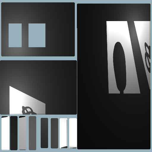
    Actually, if you�ve turned on Bi-Linear filtering in your game, then, the effect of "pixels" are reduced. But, still we smoothen out the map, to make the final image appear really smooth. If the final result (in the game) looks good without blurring the light map texture, then, you may skip the BlurThisMap procedure.

    There's another problem if we use bi-linear filtering. It's the "bleeding" problem.

    When bi-linear filtering is turned on in your game, then, whenever a pixel is chosen, the final color will not be the color from the pixel alone, but, the average of the pixels around it. (average of how many pixels - depends on the kind of filtering used.)

    As you know, some of the pixels in our texture map will be illegal. It means, that particular pixel belongs to no polygon.

    Usually, the color of any illegal pixel will be zero, since no color calculation is being done for that pixel.

    So, while rendering, whenever a pixel is chosen, the average of the color around that pixel will be considered. In this process, even the "illegal" pixels may be chosen. This is why "bleeding" happens.

    If we're using bi-linear or tri-linear filtering (which I bet we would be) in ourgame, then, we somehow got to get rid of the illegal pixels.

    Actually, we can't get rid of them. What we can do is fill every illegal pixel with a color from the closest "legal pixel". This way, during filtering, it is assured that the closest and most appropriate color is chosen.

    This way, most of the "bleeding" problems will be solved. This is what the procedure FillAllIllegalPixelsForThisLightMap does.

    One way of solving "bleeding" problem, without having to fill out illegal pixels, is to set the color of all the illegal pixels to ambient color. Even though this gives decent results and is also very inexpensive, it's not the correct way of doing it. Maybe, you can consider this method for real-time light map generation.

    Take a look at the figure below:


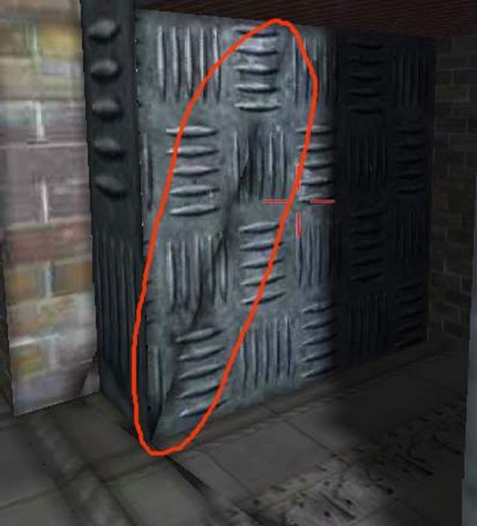
    Bleeding due to bi-linear filtering being turned on.


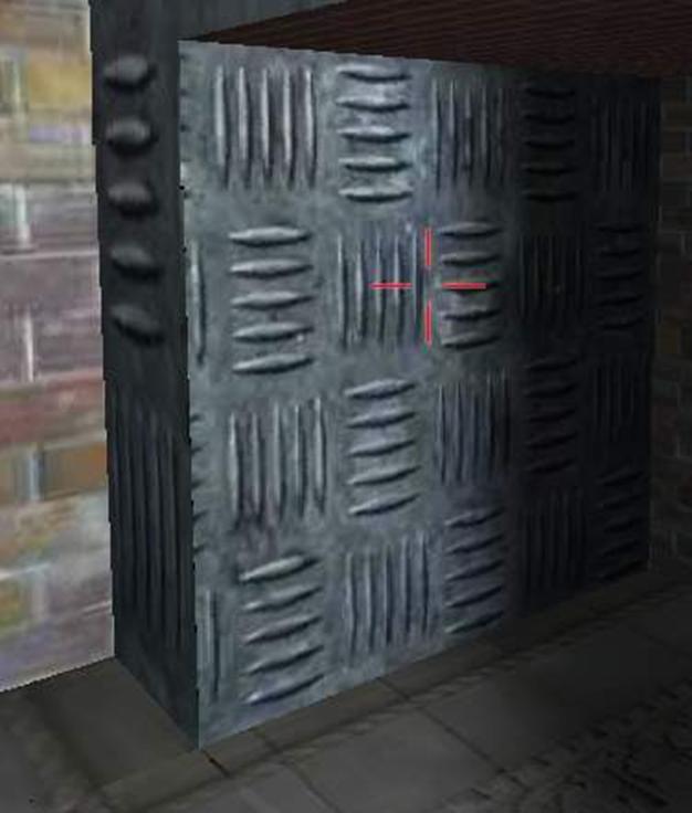
    No bleeding even if bi-linear filtering is turned on.


    Showing the lightmap:

    Now that you�ve taken so much time to calculate the light maps, it�s �display time�. Here�s the code for DirectX 8.1:

    
    // set the appropriate values for the texture stages.
    // here I�m assuming that the device supports two or more texture stages. 
    
    SETTEXTURESTAGE(device8, 0, D3DTSS_COLOROP, D3DTOP_SELECTARG1) ;
    SETTEXTURESTAGE(device8, 0, D3DTSS_COLORARG1, D3DTA_TEXTURE) ;

    // multiply SETTEXTURESTAGE(device8, 1, D3DTSS_COLOROP, D3DTOP_MODULATE) ;

    SETTEXTURESTAGE(device8, 1, D3DTSS_COLORARG2, D3DTA_TEXTURE) ; SETTEXTURESTAGE(device8, 1, D3DTSS_COLORARG1, D3DTA_CURRENT) ;

    // set the appropriate vertex shader. SETVERTEXSHADER(device8, FVF_MYVERTEXSHADER) ;

    SETTRANSFORM(device8, D3DTS_WORLD) ; // set the world matrix // set the texture for the first stage. SETTEXTURE(device8, 0, diffuseTexture) ;

    // set the texture for the second stage. SETTEXTURE(device8, 1, lightMapTexture) ;

    DrawPrimitive() ; // draw the polygons


    Winding up...


    As I have mentioned above, you have to look into Chris Hecker�s article for more explanation on some of the equations I have used.

    Some more illustration of using light maps:

    To assert the effectiveness of using light maps, a scene has been rendered with different properties / effects. Click on each of the link below to see the images:
  • A flat scene without light maps or any lighting.
  • Scene rendered with simple vertex lighting.
  • A light map that has been generated for the scene.
  • Scene rendered with a medium resolution light map.
  • Scene rendered with a high resolution light map.
  • Scene rendered with light map only, i.e. no diffuse texture.
  • Where can you go from here?
  • You can use it to light up your �un-lit� level
  • Implement dynamic light mapped lighting .. that would be cool.
  • Using the knowledge gained by using the light mapping technique, one can extend it to implement radiosity lighting.


  • Conclusion:

    With the arrival of new monster graphics cards, lighting using lightmaps may become extinct. This article does not provide you any cutting edge technology for today�s hardware, but it does provide some basic but useful information on the process of creating light maps.


    Demo:

    An interactive demo has been included with this article where you can see the practical results of this article. I suggest that you download the demo and have a look at the results your self. After you have downloaded and unzipped all the files, look into the readme.txt file for more info. Feel free to play around with the lights. In the demo, you can add and delete static and dynamic lights, change the light properties and build light maps on the fly - and see the results. It's a very good example for using light maps.
    Click here to download the demo (~2.1 MB).
    (* Editor's note: source code is not included with this demo.)


    Credits and Acknowledgements:

    Please look at Chris Hecker�s article on Perspective Texture Mapping at:
    http://www.d6.com/users/checker

    I would also like to thank my company for permitting me to publish this article. I also acknowledge the contributions of all my team members.


    Links:

    Click here for some info on light map co-ordinate generation.
    http://www.flipcode.com/cgi-bin/msg.cgi?showThread=06June2000-LightmapStorage&forum=askmid&id=-1

    Some more links to articles or docs about light maps:

    http://polygone.flipcode.com/
    http://www.flipcode.com/cgi-bin/knowledge.cgi?showunit=79
    http://www.flipcode.com/tutorials/tut_lightmaps.shtml


    Some Information about the author:

    Keshav Channa is the team lead - Engineering, at Dhruva Interactive, India's pioneer in games development. He was part of the team which ported the Infogrames title Mission: Impossible to the PC and has been an integral part of Dhruva's in-house R&D efforts. Previous articles include �Geometry Skinning / Blending and Vertex Lighting� published on flipcode.

    He is currently working on a multiplayer game for the PC. You can see his work at the Portfolio section at www.dhruva.com

    Keshav can be contacted at kbc at dhruva dot com.


    Derivation


    NOTE: The following section is extracted from Chris Hecker�s article on Perspective Texture Mapping and the derivation elaborated further.


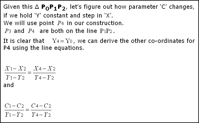
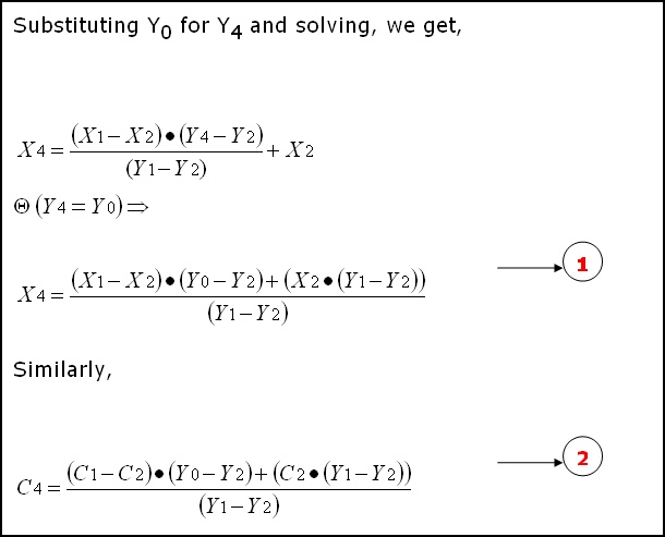
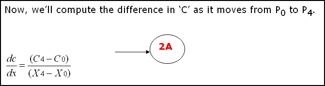
    (The equations are from Chris Hecker�s article on Perspective Texture Mapping. The only thing I�m doing from here onwards, is elaborating the derivation.) The derivation is very simple and involves plain substitution and some re-ordering.
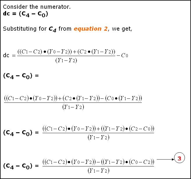
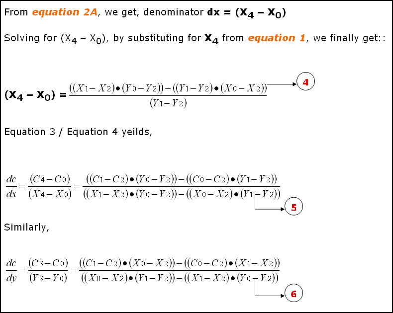
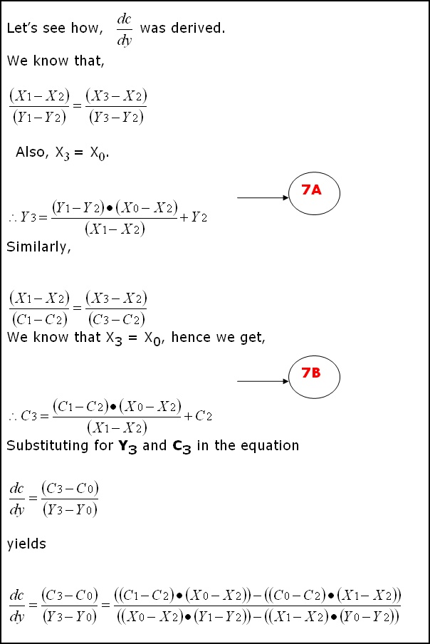
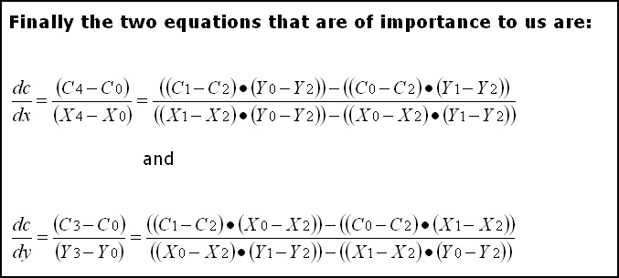


    Copyright 1999-2008 (C) FLIPCODE.COM and/or the original content author(s). All rights reserved.
    Please read our Terms, Conditions, and Privacy information.